Back to Selectron Home
©2007-2014
Charles Osborne
Latest revision: 04 JUN 2014
The RCA Selectron -- Technical Overview of the RCA Selectron
The Selectron is an electron tube (valve) digital memory device.
Described as a Selective Storage Electrostatic Memory Tube
it stores multiple two-state bits which can be selected, written, and read by bi-level control voltages
applied to internal electrodes.
The memory is fully static requiring no refresh activity after reading or during long periods of inactivity.
The major difference between -- and advantage over -- other storage electron tubes of the era is that
the Selectron is fully digital.
Other devices such as the Williams-Kilburn tube and MIT's more complex
storage tubes for the Whirlwind
computer require precise analog selection and control voltages.
Analog storage tubes deflect a single beam of electrons to multiple storage locations.
The support circuitry for analog tubes is required to accurately and repeatedly guide the single beam
over a large area over long periods of time.
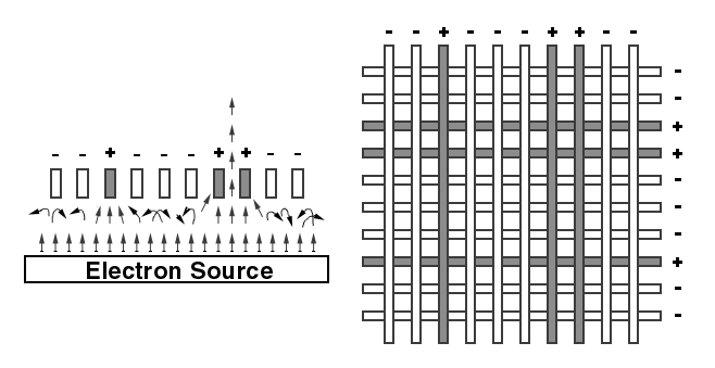
The Selectron simply gates multiple fixed electron beams on-or-off using bi-level voltages
which do not require high precision.
The tradeoff is that the Selectron tube is structurally complex to build but electrically simple and reliable.
The diagram shows a simplified diagram of the internal elements of a Selectron tube -- four functional segments are depicted. The process begins at the top where electrons are emitted from the heated Cathodes. If a window bordered by all four adjacent Selection Bars are at a voltage more positive than the Cathode potential electrons will pass toward the Collector Plate. The Collector Plate being more positive than the Cathode passes the electrons through its openings. The Storage Eyelets are electrically insulated from, but capacitively coupled to, the Writing Plate by an insulating sheet of Mica. Pulsing the Writing plate while electrons are flowing toward a storage eyelet permits changing the potential of the eyelet. The individual eyelets will each maintain, by means of secondary emission, one of two stable potentials: That of the Cathode which will block electrons or that of the Collector Plate and passing electrons.
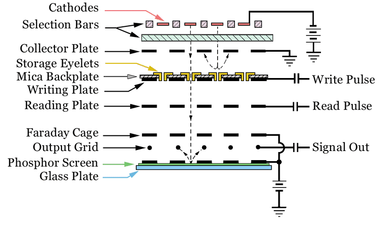
An eyelet at the potential of the cathode will repel electrons back to the collector plate; An eyelet the potential of the collector plate will allow electrons to pass through. The Reading Plate either inhibits or allows passage of all electrons flowing through the storage eyelets. Electrons then pass through the holes in another plate comprising the front of a Faraday Cage. The Faraday Cage both isolates the signal Output Grid from interactions from the potentials on all other tube elements and accelerates entering electrons which have passed through the storage eyelets. Once inside, the electrons hit a Phosphor Screen target giving two useful benefits: The added energy from being accelerated into the Faraday Cage causes the phosphor to glow when struck providing a visual readout of the pattern of electron flow through the many eyelets. When the incoming electrons strike the phosphor screen many additional secondary electrons are generated, increasing the electrical signal collected by the signal grid wires.